
The traction inverter is the middle unit on the Nissan Leaf drive stack. It takes high voltage DC from the PDM and creates the three-phase drive current for the Nissan Leaf EM57 motor.
This page collects information on the mechanical, electrical and software interfaces of the Gen 2 80 kW unit.
Electrical interface
The inverter is driven by 12 V and draws around TBD A during full operation.
The high voltage inputs contain a considerable amount of capacitance and should not be connected to the battery without pre-charging first.
Connector
The main signal connector on the Gen 2 80 kW inverter seems to be a proprietary connector. There are indications that the same has been used for the Toyota Prius Gen 3 inverter and has the Toyota part number G9260-47010. I will try to order one and confirm this — see the openinverter thread linked under References.
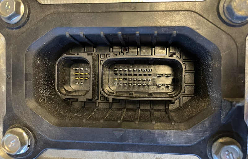 Nissan Leaf Gen 2 inverter signal connector.
| Part | Inverter (Male) | Wire Harness (Female) |
|---|---|---|
| Housing, 36p | TBD | Toyota G9260-47010 |
| Housing, 13p | TBD | Toyota G9266-47010 |
| Terminal 1–45 (small) | TBD | TE 1612290-1 |
| Terminal 46–49 (large) | TBD | Yazaki 7116-4025 |
Pinout:
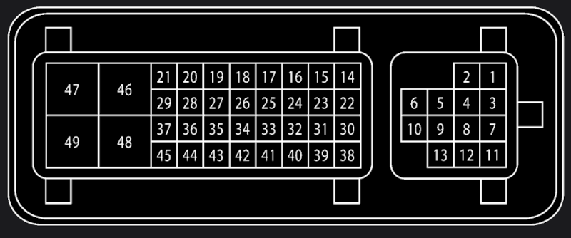 Nissan Leaf Gen 2 inverter signal connector pinout.
Not all pins are populated.
| Pin | Name | Description |
|---|---|---|
| 14 | EV-CAN High | TBD |
| 15 | EV-CAN Low | TBD |
| 17 | Resolver S2 | TBD |
| 18 | Resolver S4 | TBD |
| 19 | Resolver R1 | Excitation coil? |
| 20 | Resolver S1 | TBD |
| 21 | Resolver S3 | TBD |
| 27 | Resolver R2 | Excitation coil? |
| 42 | Ignition | Connect to Battery+ when ignition is on |
| 44 | Motor Temp GND | TBD |
| 45 | Motor Temp | TBD |
| 46 (large) | B+ | Battery+, fused with 10 A |
| 47 (large) | B− | Battery−, connect to GND |
| 48 (large) | B+ | Battery+, fused with 10 A |
| 49 (large) | B− | Battery−, connect to GND |
Since the high power 12 V supply is fused at 10 A, 1.5 mm² should be enough.
Interlock
The inverter contains an interlock circuit that breaks a connection if the top lid of the inverter is opened. The interlock pins are TBD on the signal connector. The interlock is wired in series with the rest of the high-voltage interlock; see the Safety architecture post for how that fits into the overall safety system.
CAN interface
The inverter is on the EV-CAN network — a standard ISO 11898-1 CAN bus with 11-bit identifiers at 500 kbit/s.
To keep the inverter happy, three CAN frames need to be sent periodically:
- ID
0x11A - ID
0x1D4 - ID
0x50B
Start procedure
- Switch on 12 V power.
- Initiate CAN communication.
- Start pre-charging.
- Connect HV power.
Stop procedure
- Request 0 Nm of torque.
- Disconnect HV power.
- Switch off 12 V power.
Cooling
The inverter needs coolant flowing through the cooling circuit. More info TBD.
References
- Service manuals at NicoClub.
- Reverse engineering by 8Dromeda.
- openinverter forums: (Prius) Gen 3 inverter connector.